Chris Thompson   USyd Lectures Listing

Anaesthesia Breathing Systems

Schimmelbusch

Schimmelbusch Mask

WatersToAndFro

Waters To & Fro system

1. FUNCTIONS

  • delivery of anaesthetic gases and vapours;
  • oxygenation of the patient; and
  • CO2 elimination.


2. CLASSIFICATION

  • Open - FGF from atmosphere alone (no circuit).
  • Semi-open - Fresh gas from atmosphere, some apparatus e.g. Schimmelbusch mask, hand cupping gas from T-piece +/- added O2 etc.
  • Closed - Closed to atmosphere; FGF = uptake, CO2 removed.
  • Semi-Closed - Closed to atmosphere; FGF > uptake; excess scavenged; can be
    • Semi-Closed Non-Rebreathing (typical ICU ventilator) or
    • Semi-Closed Rebreathing (e.g.. typical circle circuit);CO2 removal by absorber or FGF

Alternative - Conway

  • Without CO2 absorbers - Mapleson type, Resuscitation Bags
  • WIth CO2 absorbers - Circles, Waters (to-and-fro)


3. MAPLESON CIRCUITS

circuitsall1

1. MAPLESON A - (Magill) CIRCUIT

FGF enters at the end remote from the patient, and there is a Heidbrink one-way pop-off valve at the mask end. Originally C-type systems were common; Magill designed the A circuit to get the bag away from the patient during faciomaxillary surgery.

MagillSpont1 

Magill in spont respiration
(the diagram is incorrect in two places)

(a) Spontaneous ventilation

The patient inspires whatever is in the tube, using the bag as a volume reservoir.

On expiration, the bag refills from a combination of expired gas going back up the corrugated tube and incoming fresh gas. When the bag is full, exhaled alveolar gas is vented from the exhale valve, and then during any expiratory pause, FGF pushes the remaining alveolar gas out.

Theoretically FGF = 0.7 x Valv should prevent significant rebreathing because deadspace gas (fresh) is not wasted, but FGF = VA more reliably prevents rebreathing.

Tube volume must exceed (Vt-Vd) or alveolar gas could contaminate the bag.

Inadequate FGF causes rebreathing . Difficult to detect from the CO2 waveform alone - all that happens is that the rapid fall on inspiration is delayed. If VA exceeds tubing volume, CO2 enters the bag and will be seen on inspiration on the capnogram.

(b) Controlled ventilation

If the anaesthetist fully closed the valve while squeezing the bag and didn't open it until just before the bag filled, this circuit would be OK. More commonly the valve is partially closed - enough to permit adequate tidal volumes despite parallel loss of gas out the valve. FGF must be increased to compensate for gas lost during inspiration - typically 2.5x minute ventilation.

c) the Lack system

A co-axial Magill, with the expiratory valve brought coaxially back to the Fresh Gas outlet. Not popular due to inefficiency during controlled ventilation.


MaplesonBandC2. MAPLESON B & C SYSTEMS

Inefficient. Once the bag is full during expiration, fresh gas is vented.

Not suited for spontaneous breathing - rebreathing is inevitable (with CO2 entering the tubing or bag) unless FGF exceeds peak inspiratory flow rates (3xMV).

The C circuit is compact and was used for short transports before self-inflating bags became available. Acceptable CO2 levels could be achieved with a FGF of 2 x MV and mild hyperventilation. If the cylinder became empty ventilation was impossible.


maplesonD
 Coaxial = Bain

maplesonE
Ayer's T-Piece

maplesonF
Jackson-Rees Modification

3. MAPLESON D, E and F SYSTEMS

FGF enters at patient end.

D system has a relief valve proximal to the bag. Bain circuit is a co-axial D introduced in 1972 (Bain and Spoerel).

E and F are functionally identical.

Spontaneous breathing: inefficient. Inspiration is from Fresh Gas Flow and/or tube contents. If FGF > PIFR, all inspired gas will be fresh. If there is an expiratory pause, fresh gas pushes exhaled alveolar gas down the tube during the zero flow period, and FGF requirements are reduced somewhat. If no exp.. pause, needs FGF > 2.5xMV. With exp. pause may be OK as low as 100ml/kg. Most patients can readily manage a small inspired CO2 load. CO2 during capnometry inspiration indicates a need for higher flows.

Controlled ventilation: more efficient. Significant mixing occurs and CO2 is 'washed out' by FGF. Provided that VA is adequate or slightly increased, CO2 washout depends on FGF, with normal CO2's at an FGF of 70ml/kg.

Tubing + bag volume must exceed Vt to prevent air entrainment (unless functionally extended by a scavenging hose).

Jackson-Rees modification of Ayre's T-Piece (Mapleson F)

Original T-piece by Phillip Ayre in 1937 for children; ventilation by occlusion of the open ended tube with fresh gas entering at a right angle to the tube..

Modified by Jackson Rees in 1950's by adding an open-ended 500 ml bag to allow respiratory monitoring and/or assistance, and a parallel entry of the fresh gas line at the patient connection.

Commonly used for paediatrics, esp.. neonates:

  • light weight;
  • low resistance -no valves.
  • low deadspace
  • good 'feel' of the lungs
  • can be used for both spont and controlled ventilation

Deadspace is determined by the distance between fresh gas inflow point and the face. Specialised neonatal T-pieces direct FGF directly at the lips..

Disadvantages
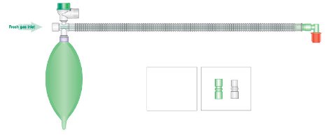
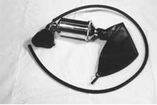
  • High FGF (esp.. in adults)
  • Much less efficient than a circle system
  • Dry gases unless humidified
  • Scavenging issues
  • can't be used for controlled ventilation with some modern machines

Bain Circuitbain

Outer tube 22 mm diameter. 1.8m long. FGF travels to patient end via thinner 'coaxial' inside the expiratory tube.

Advantages :

  • light weight
  • compact at ETT end
  • no valves to fail

Disadvantages

  • checking inner tube isn't so easybain2
    • O2 flush should empty reservoir bag by venturi effect
    • occlude distal end and observe drop in rotameter bobbin/s
  • unrecognised detachment of inner tube at machine end causes CO2 rebreathing
  • very uneconomical compared to circle, esp.. in spontaneous breathing


4. CO2 ABSORPTION (CIRCLE) CIRCUITS

Semi-closed and closed operation possible.

1. Absorber and absorbent

Canister containing absorbent may be single or dual, of metal, glass or plastic. Air space typically 50% of total. Larger cross-sectional diameters allow less turbulence with reduced resistance and less dust.

Well packed canisters allow diffuse spread of gas through the absorbent, rather than in a columnar fashion.

Bypass mechanism can isolate absorber from circuit and allow PaCO2 to rise without decreasing minute ventilation.

Advantages of CO2 absorption

  • lower FGF, improved economy;
  • less pollution;
  • heat and moisture are conserved;
  • flammable gases and vapours (historically) contained.
  • inhaled mixture composition is more constant.

Soda lime

  • Ca(OH)2 plus 4% NaHCO3, 1% KOH, 14-19% H2O.
    • Calcium hydroxide free soda lime reduces compound A production markedly
    • Desiccated soda lime can produce carbon monoxide
  • Silicates prevent powdering.
  • Fresh soda lime has pH = 12; decreases as CO2 s absorbed.
    • - white S/L contains ethyl violet, critical pH = 10.3;
    • - pink S/L contains phenolphthalein, pHcrit = 7 - becomes colourless.
  • Granule size 4-8 mesh; irregular surface shape to enhance absorptive area.
  • 450g soda lime absorbs 47 litres of CO2 minimum
    • ~4.5 hrs absorption at VCO2 = 150 ml/min.
  • FGF of 50% MV increases the duration to ~ 8 hours.

Heat in the canister is heat of neutralisation; liberates water vapour; may indicate high patient VCO2 e.g. MH

Signs of exhaustion

  • Inspired CO2 on capnometry
  • colour change
  • warm at the top, cool below
  • signs of hypercapnoea in the patient.

2. Fresh gas inlet

Usually between CO2 absorber and inspiratory valve.

3. Uni-directional valves

  • at least 2 in each circle system
  • present on inspiratory and expiratory limbs, typically within the absorber
  • 2 main designs:
    • ceramic or steel disc on annular seat, anchored within a cage, or
    • "flap" (ambu type) valves.
  • low resistance desirable, therefore:
    • large surface area
    • light weight
    • lift-clearance of ~ 1/2 valve seat diameter.
  • Problems:
    • additional resistance
    • incompetence (sticking at an angle - wetting, electrostatic attraction, poor design)
    • leaks around seals of the domes

4. APL (adjustable pressure limit) valve

  • Usually a spring loaded disk occluding flow, turning the knob clockwise increases pressure on the disk
  • Manual ventilation:
    • Adjust so that losses during inspiration ≈ FGF
    • Should open at a specified pressure and be airtight below that
  • Spont. respiration:
    • Should be set fully open
    • Should demonstrate low resistance when open
    • Perceived resistance to exhalation usually increases markedly once bag is full and all gas must exit the APL
  • Mechanical IPPV
    • must be closed completely or isolated, either manually or automatically

5. Pressure gauge/s

  • Aneroid gauges typically attached near insp. limb in mechanical machines
  • Electronic transducers in more recent machines

6. Breathing hoses

  • ISO 5356-1 specifies 22mm / 15mm conical tapered fittings , leak <50ml/min, compliance <1ml/cmH20/m, kink resistant so that resistance does not increase by more than 50% when pulled into contact with half a 2.5 cm diameter cylinder.
  • 1m of 22mm hose has an internal volume of about 450ml
  • Compliance typically 0.7ml / cm H2O / m (i.e. 2x3m hoses at 10cmH2O = 40ml). Compliance reduces actual delivered tidal volume compared to bag movement and during spontaneous breathing allows a little gas flow from both inspiratory and expiratory hoses ('sucking them flat')
  • Resistance typically < 0.5 cmH2O at 30 l/min in adult hoses

7. Reservoir bag

  • permits manual ventilation, manual assessment of compliance etc
  • volume buffer
  • indicator of adequacy of fresh gas over leak
  • sizes from 500 ml - 3 litres.
  • small bags on 15mm circle circuits provide excellent feel of the lung when hand-ventilating neonates
  • can hold 10x nominal volume before bursting
  • pressure rises to peak of about 50-70cmH20 but falls late with massive distension

8. "Y" Piece

Standard 22 mm male connections for breathing hoses. Patient connection port is a 15 mm female fitting or a 15 mm female port coaxial within a 22 mm male fitting. Common source of leaks.

9. O2 Analyser

  • "T" fitting located at the inspiratory limb of the circuit or
  • via gas sample line

10 Ports

  • "Common gas outlet" coaxial 15/22 mm; may have some physical means to prevent unintended disconnection. Should not be used to provide supplemental oxygen to the patient. Easiest way to connect a manometer to the machine to test for backbar leaks.
  • I & E ports on circle 22 mm male ± 15 mm female; should not point straight down
  • Reservoir bag 22 mm male; should point downwards
  • ETT connector 15 mm male
  • Scavenging system 19 mm conical.
  • Ventilator connection
    • Either manually connected to the end of the breathing hose, or
    • Internally located and automatically activated when a 'vent' mode is selected

See Also: Equipment notes by Mark Finnis
Last updated Tuesday, December 15, 2020
Comments? please use this form.