|
ELECTRICITY AND ELECTRICAL HAZARDS 1) Basic Electrical Concepts Voltage: the 'push' on electrons to move through a conductive medium
VOLTAGE
Voltage is a measure of the electrical potential difference between two points; the fluid analog is pressure. Voltage means an accumulation of electrons at one point compared to another, and is a measure of the 'force' available to generate current flow. Voltage sources include static electricity, power distribution wires, mains electricity, batteries, right down to biopotentials across cell membranes and small voltages on signal sensors like microphones, pressure sensors etc. Higher voltages will push more electrons along a wire of given resistance, and can arc across greater distances, than lower voltages. Lightning is static electricity accumulating on clouds, and can arc across great distances. Ordinary static electricity disspates by corona effect and typically cannot build up meaningfully in humid environments. While static electrical accumulation can be of very high voltage, it does not provide a 'store' of electrons at that voltage, and cannot maintain the voltage when the electrons are drawn off. When a potential difference is applied to one end of a copper wire, the electrical field propagates down the wire at the speed of light, and, if they can find a path back to the other end of the electrical field, electrons pop out the far end. For electricity to flow, there must be a 'circuit' by which electons can flow down a conductor from a point of higher voltage to a point of lower voltage.
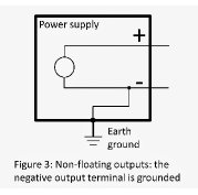
“Earth-referenced supplies” Australian standard 240V AC mains supply is 'earth referenced'. There are three wires: an active wire at 240 AC potential difference from ground, a 'neutral' wire for returning current to go back to a common ground point (typically a tap or grounded copper pipe) a 'ground' wire for safety puposes, connected to any metal chassis around appliances ,etc Electrons from the active wire are ground-seeking - they will run through whatever path they find easiest to get to ground. The active wire is 240V AC higher in potential than either the intended return wire (the neutral wire) or the backup safety wire (the ‘earth’ wire). Current will only flow along the active wire when it finds a path to ground. This type of supply is ‘earth-seeking’ or ‘earth-referenced’. Provided there is no ground path, it’s OK to touch an active wire, though it will hurt (see capacitance, below). On the other hand, if your body is connected between the active wire and a half decent connetion to ground, current will flow, and you may die.
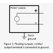
“Floating supplies” Floating electrical power supplies have two wires that are ‘hot’, but only in relation to each other. Each wire is only active when compared to the other. They ‘float’ in relation to ground - neither is ground-seeking. A way of visualising this is to imagine a battery floating in space. You can touch either end to ground, but no current will flow, because the electrons are only interested in getting to the other end of the battery, and don’t care if only one end is connected to ground. Isolating transformers work by converting a 'ground referenced' mains supply to a 'floating' supply. You can then touch either 240V wire after an isolating transformer without any great concern, even if you hook yourself up to ground, because neither wire on its own is trying to push electrons to ground. The degree of isolation refers to the extent to which a floating supply is truly ‘floating’ or ‘isolated’ from ground, or the quality of a resistance or insulation between two things that are supposed to be electrically separate. CF patient circuits are highly isolated from ground, so that even if the patient is directly connected to ground seeking 240V, there will not be enough current to cause even a microshock. To achieve this degree of isolation, special floating, non-grounded, power supplies are used insde CF equipment.
INTERNAL RESISTANCE Voltage does not provide any indication of how many electrons are available to be continuously delivered from a voltage source (the 'capacity' of a battery is not measured by voltage), nor how effectively a voltage source can maintain that voltage while current is drawn from it. Static electricity at 50,000 volts from your car on a dry day may cause a sharp 'jab', but not much else, whereas 240V mains electricity can kill instantly and will keep delivering the power to 'cook' you from the inside out. Likewise, a large 12V car battery can provide enough energy to melt a thick wire, but ten little AAA batteries joined together to make 12V will not be able to do the same thing. This is because power delivery depends on the ability to maintain the voltage while delivering electrons. Static electricity has a small number of electrons at high voltage stored on a 'capacitor'. Other than those stored on the surface of the capacitor, the supply of electrons is limited. Typically the absolute number of electrons is very small. Since they cannot be replenished, all you get is a very brief spike of current. Assoon as the electrons leave the source, the voltage quickly falls to zero - after a spike so brief as to be trivial. In contrast, mains power supplies are intended to deliver a lot of electrons (ie high currents) with no drop in voltage, and to keep on delivering the same power with no easing off over time. One way of thinking about the ability of a voltage source to deliver electrical current (and deliver power) is to imagine that there is some internal impediment to the delivery of current - an internal 'resistance' to electron flow. Physically small batteries with high internal resistance will suffer voltage 'droop' under load more quickly than larger batteries with less internal resistance. Supplies with high voltage and high current capability - eg mains voltages and large car batteries - are more dangerous.
Table 1: voltage ELECTRICAL ARCING Voltages can 'arc' across air, and the spark can ignite flammable gases. The distance in which a spark can bridge a voltage gap in dry air depends on voltage. Air breaks down at about 30kV per centimetre around spherical electrodes. Typical arc distances between spherical electrodes are 3mm at 10kV and 2cm at 50kV. Sparks form more readily from needle electrodes, traversing gaps of 1cm and 5cm respectively at 10kV and 50kV. Diathermy works in these voltage ranges - hence the sparking and arcing. A 'spark' from a car body to you on a dry day may discharge 20-200 millijoules of energy. Static electricity with that much energy can accumulate on woolen fabrics or on people walking on non-conductive flooring in dry weather quite readily. Spark energy from a discharging capacitor is E = 0.5* CV^2 in joules where C is the capacitance storing the energy in Farads and V the voltage. Human capacitance is low eg 100pF (ie 100 x 10^-12F). But since voltage is squared,10kV of static electricity on even such a tiny capacitance can deliver 5 millijoules of energy. As little as 2 millijoules can ignite a flammable hydrocarbon gas mixture, eg ether or petrol. This much energy is readily available from static electricity. Probably a good idea to avoid ether, and to short yourself to the car body before filling with petrol :-)
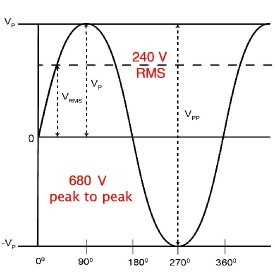
AC vs DC Direct current is what we get from a constant voltage source - the voltage is constant and does not change over time, eg a simple battery. Alternating voltage means that a voltage that is constantly changing. It can be changing randomly, examples of which include signals like the EEG signal or sound as picked up in a microphone, or it can change steadily in a predictable sinusoidal fashion, as in mains electricity. Mains power supply in Australia is a sinusoidal waveform at 50Hz, The voltage of a mains power delivery system is expressed as the RMS (root mean square) voltage. A given RMS voltage, assuming the same internal resistance, will be delivers the same amount of power as the same DC voltage. A light bulb will glow just as brightly when connected to a 240V AC mains power supply as it would on a 240V DC power supply made from multiple car batteries. Since power is proportional to the square of the voltage, the RMS calculation involves getting the square root of the time-weighted average of the square of the instantanous voltage. (ie Root of the Mean of the Squares). 240 V RMS means 680 Volts peak to peak. The main advantage of AC for power delivery is that it is not subject electrochemical damage to metals through galvanic corrosion. DC voltages above the anodic potential differences will result in serious corrosion, as happens to copper telephone wires exposed to moisture (telephone wires are at 70V DC to power the handset, which the audio itself is AC).
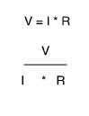
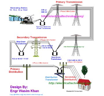
Current Current is a measure of the number of electrons flowing down a wire per unit time, expressed as Coulombs per second or Amperes. One coulomb is 6.24x10^18 electrons. Ohm's Law says that the amount of current flowing through a resistance is proportional to voltage and inversely proportional to resistance. A voltage of 1 V causes a current of 1 amp to flow through a resistance of 1 ohm. More voltage = more current; more resistance = less current. Current flowing through resistances generates heat. For any given voltage, the amount of heat falls as resistance falls. The amount of heat is proportional to the power dissipated and is expressed as watts. For any given resistance, the greater the voltage, the greater the current. Much less current is needed at higher voltages to deliver the same power. Large overhead high tension wires between power stations and cities are designed to operate at high voltage - 138 - 768 kV - keeping the weight of the copper wire down. These cables will arc over distances of up to half a metre.
Power Power is the product of voltage and current, expressed as watts (joules/sec). ie Power = Volts * Amps Using Ohm's law, Power = I^2 * R or Power = V^2 / R A light bulb is a small wire with pre-determined resistance, calculated to allow an amount of electrical current to flow such that the dissipated power makes it gets hot enough to glow. The following example shows how proportionally current is required to deliver the same power at higher voltages: A 50W 12V halogen light globe with a resistance of 3 ohms pulls a current of 4 amps; 4 amps * 12 volts = 48 watts. A 50W 240V incandescent light globe has a resistance of 1200 ohm, resulting in a current of about 0.2 Amps; 0.2 * 240 = 48 watts. A 240V globe will barely glow when connected to a 12V car battery, but converselely a 12V halogen bulb connected to 240V will immediately go bang! and melt the wire inside.
Resistance Resistance is the tendency to resist the flow of electrons down a conductor (or across a tissue) in response to an applied voltage. It's easiest to think about resistance in DC terms, as per the above examples, and it can be considered in DC terms for low frequency RMS currents like AC signals. But for AC signals, particularly higher resistance AC signals, Impedance is the better term. That's because high frequency AC signals can pass differently through capacitors and inductors than DC signals. Impedance is the term used as the equivalent of of resistance at a given frequency for a given inductive or capacitive load. Both impedance and resistance share the units of Ohms (Ω). One Volt results in a 1 Amp current if the resistance (or impedance) is 1 Ohm. Copper wire has very, very low resistance. Salty water is not such a bad conductor, being is one ten-millionth as good as copper for an equivalent sized piece of material. People are bigger than wires. A 10x10cm piece of muscle has a resistance only 1/1000 that of a 1mm square copper wire, which actually is quite a low resistance. Insulators have resistances of millions to billions of times greater than salt water. Let's say you touch an 'active' clothes dryer and ground yourself to a tap. A resistance of 10kOhm (typical value for reasonable surface area of dry skin) with an applied voltage of 240V allows a current of 240/10,000 A or 240mA to flow – enough to cause tetanic muscle contraction, make it impossible to let go of the tap handle or breathe, and will deliver 60W of heat through the muscles, resulting in overheating and burning of the muscle fibres and nerves under ths skin. You will probably die first from asphyxia or VF. With moist skin at a resistance of less than1k, death from VF would be immediate, sparing you the agony of being slowly cooked by >600W of heat. Modern medical patient circuits have input impedances of >1MΩ, so if you connect yourself to 240V via one of these, the max possible current is 240/1,000,000 or 0.24mA, which you can feel but won’t hurt you (unless it goes directly to the myocardium).
Resistances in series The total resistance of two resistors in series (one after the other) is the sum of both. ie Rtot = R1 + R2. Hence when two resistances appear in series, and one is much greater than the other, the highest resistance limit the current flow. Air gaps, plastic boxes, and electrical insulation around wires provides a high resistance between active conductors inside and anything that would otherwise contact those conductors. Insulation is the primary way we make electricity safe.
Resistances in parallel If two resistors are connected side by side (in parallel), electricity flows proportionally down the path of least resistance. The formula is 1/Rtot = 1/ R1 + 1/R2. Two resistances of 1 ohm in parallel result in a total resistance of 0.5 ohms, and the current splits equally through both. If one resistance is 1000 ohms, and the other just 1 ohm, the overall resistance is near enough 1 ohm, and only 1/1000th of the electricity goes through the 1000 ohm resistor. An intact grounding wire will provide a much easier path to ground for leakage currents than through a person, and minimises the amount of current that would otherwise flow through the patient.
Capacitance The ability of large conductive surface areas to store electrons when a potential is applied to them. Two large plates close apart (but separated by an insulator) form a capacitor. A one Farad capacitor stores one coulomb of electrons for a 1 volt potential. This has the ability to do 1 joule of work when discharged (1A x 1V). The potential energy of these electrons is stored in the electrical field between the two plates. Anything that has a large surface area is capacitively coupled to things around it. Clouds are very big capacitors, and when they discharge you get lightning. Capacitors do not let DC current flow through them, but alternating currents, particularly high frequencies, can flow through them. The impedance of a capacitor (its apparent resistance) falls as the frequency increases (Zc = 1/2πFC Ohms). Hence, a capacitor has a frequency-dependent resistance (impedance). All patients are coupled by capacitance to ground, and people have capacitance on their own, so you always feel some kind of tingling when you touch 240V, even if there is no direct physical connection to ground. Metal equipment casings are capacitively coupled to any components within. If the internal electricals are supplied by an earth-referenced power supply, this coupling results in ‘earth leakage’ currents that can exit via the frame. The earthing wire should normally provide a low resistance pathway to ground for these leakage currents, without which electrical tingling may be felt.
Effect of 50 Hz electricity on muscle Microshock Fibrillation 0.1 mA (only when directly applied to muscle) Sensation depends on current density. Small currents over large areas are not felt as well as the same current over a smaller area. The myocardium is most sensitive to 30-100Hz electricity, so mains at 50Hz is ideal for inducing fibrillation. Higher frequencies (ie, diathermy), DC electrical current, and AC which does not pass through the heart do not cause fibrillation but rather heat up and burn the muscle they flow through, sparing skin and fat. Microshock is a term describing the induction of ventricular fibrillation by small electrical currents (below the threshold of skin sensation) when applied to very small areas of ventricular muscle, usually by vascular catheters or wires. It requires a small area of contact with heart muscle so that the current density is high despite low current. Nerve stimulator tetany is at 50Hz, but the pulses are only 200us wide, whereas mains power pulses are effectively 10ms wide; the same amount of mains current feels 50 times stronger.
3) Safety featrures of the mains electrical supply Typical problems:
Class Z areas: Characteristics:
The Earth Wire: The earth wire must always be in good contact with all metal parts of any appliance the user may touch. Should the equipment become faulty by the active wire touching the case, then current will rush to earth, smoke will rise from the equipment, and if the current is very high the fuse in the active line will blow, disconnecting mains power from the faulty appliance. Without the earth wire, this fault would go undetected, allowing high current to flow through the patient whenever the patient formed a circuit to ground. Standards limiting current in any circuit are vital to prevent excessive heating of the power supply wires leading to fires. Should the leak to the metal parts of the appliance not be enough to blow the fuse, then the earth wire will drain the electricity away to earth by a low-resistance pathway. The user will be unaware of the potential dangerous nature of the device. If the earth is poor and a patient circuit to ground occurs, then the user may feel a "tingle" or a more substantial shock. The presence of a good earth wire at all power points is the main safety feature of Class Z areas. It may become faulty due to corrosion of the sockets, leads, or extension cables, bending of the pins within the wall sockets, and corrosion or poor installation of the electrical supply. The high resistance of normal dry skin helps protect patients from electrocution by many of the failures which may not be sufficient to blow the fuse. Danger is particularly high when the user is working in wet surroundings (low-resistance pathway to earth) or using power tools or extension leads. Small domestic Earth Leakage Core Balanced relays are available for use in extension leads and in hazardous (ie wet) areas, and can in fact be installed as well as or instead of fuses in the home fuse box. These provide very greatly reduced risk of electrocution, by quickly disconnecting the electricity in the event of even a minor failure (more later). 2) Class B areas. Characteristics:
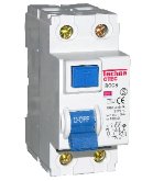
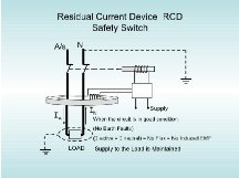
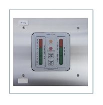
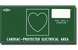
The sort of minor equipment failures where there is a leakage of power through the earth circuit (but not enough to blow the fuse) may be lethal once the patients protective skin resistance is reduced. All patient care areas where the usual skin resistance is reduced owing to the presence of low-resistance patient circuits, ie on ECG machines, diathermy devices, etc, must therefore have special precautions to reduce the risk of electric shock. Residual Current Devices (RCD's) RCD's's are the cheaper way to do this. Since normally all the current leaving a piece of electrical equipment goes back to ground by the Neutral wire, then the current flowing through the Active and Neutral wires should at all times be equal. Should a fault exist in which electricity is leaking to ground by any other route, then the currents in the Active and Neutral wires will no longer be equal, and under these circumstances the RCD will be "tripped" and both the Active and Neutral supply will be disconnected from the socket providing power to the faulty device. The RCD will disconnect power within 10 to 20 milliseconds (ie a half cycle) when a leak current of 5 to 10 mA or less is detected. It will protect against 99.9% of cases of macroshock and identify faulty equipment immediately.. An audible alarm will sound and a loud thump will be heard when the relay is tripped, and power can only be restored manually, by pushing the switch back to the "on" position. Usually a test button is available to check the correct operation of the RCD. The RCD will not detect faults in which electricity passes through the body and back through the Neutral wire, however these are very infrequent. It will not protect against microshock as up to 10 times the required current for fibrillation may pass through the patient without tripping the relay. RCD's are generally wired to several power outlets, and if tripped will disconnect power from them all, and keep on doing so until the faulty device is removed. This is not desirable in some patient care areas, where a different type of system may be used. Isolating Transformers and Line Isolation Monitors. These are the more expensive alternative to RCD's and are widely used in operating theatres because they do not disconnect the power when a fault is detected, yet provide safety should such a fault exist. The first component is a large transformer (the Isolating Transformer) mounted in the wall cavity which converts the earth-referenced mains supply to a "floating" supply. The floating supply provides 240V between two active wires, but because the supply is not earth-referenced, the presence of an earth circuit through the patient or anyone else is perfectly safe and no current will flow. All the circuit to earth does is to reference the floating supply to earth; no current actually flows through the earth connection. The Line Isolation Monitor continually checks that the floating supply is not earth-referenced, and indicates on a dial how much current could flow to earth if there was an earth connection. If the potential earth current would be more than 5mA an alarm will sound, alerting the anaesthetist to the presence of a loss of the "floating" nature of the supply. It does this by intermittently connecting one of the two active wires to ground through a very large resistance. If the other wire is connected to ground a circuit will be formed and current will flow, and this indicates how much current would flow through the circuit if either of the two active wires are connected to ground. As with an RCD the device will not alarm under 5mA, so microshock may still occur unnoticed, however macroshock is very unlikely; only current flowing through the patient from between the active wires will no be detected. Class A - 'cardiac protected' - Areas Characteristics:
Only these areas should be used when intracardiac conductors are present. All potential sources of leak current should be equipotentially earthed by special low-impedance green cables, and this includes the anaesthetic machine, IV poles with IMEDs on them, etc. The only meaningful difference between 'cardiac protected' areas and body protected areas is the inclusion of equipotential earthing. If you don't use equipotential connectors, there is no other benefit. Equipotential earth conductors are special ultra-low resistance connectors for use between equipment and the wall, and inside the wall a set of heavy duty earthing connectors. These are very expensive to install. When used, they greately enhance the safety of the grounding, which can easily become dodgy when power cords are pulled sideways in the sockets, spreading the pins apart on connection. Most fixed monitoring in ICU and the OR, and all stand mounted pumps etc (ie all other than double insulated equipment )should be EP earthed to maximise safety. However now that the patient is rarely actively earthed, and given that nearly all monitors have cardiac protected patient circuits, the risk of intracardiac electrocution is very small even if the earth wire in the cable is not very good. 4) Saftety features of electrical equipment a) General Construction The device should be manufactured so that the risk of the casing of device or other conductive part becoming active or partially active without the user noticing is small. If the case became active and the earth fail, a person who completes a circuit to ground may be electrocuted. Correct construction of the device, ie proper attachment of power wires inside the casing, the use of double-insulated design techniques, etc, minimise this risk. There are three classes of equipment based on these general construction considerations Class 1: Earthed All these devices must be earthed. All electrical devices leak electricity to their cases and this will seek a return path to ground. This is normally provided by the earth wire. There is a limit to the allowable leakage down the earth wire, so that should the earth fail, the patient would not be at risk of electrocution from the case (unless there was another fault as well). Most people would feel a faint tingle from 500μA, and may get the feeling that something is wrong. Type of patient circuit Earth Leak (max)
Class 2: Double-insulated This equipment need not be earthed as there are no conductive parts on the exterior capable of carrying current. Often the internals are earthed, and an earth leak current will then occur. Class 3: Low-voltage This is less than 40V DC. If AC is used then a special isolated transformer must be used. Low voltage sources (particularly DC) are very safe. b) Patient Circuits Normally skin resistance is quite high and this is a safety barrier to electrocution. This barrier is lost by many patient monitoring circuits and by having a wet patient. Small currents, ie the normal leakage current of the device, may be hazardous when they flow through low-resistance pathways to ground. This potential problem is reduced in all devices with patient circuits by including a very high resistance in the device, to limit the maximum current that could possibly flow through the patient to extremely low levels.
Class BF devices will conduct up to 5mA through their patient circuit in worst-case conditions, and while this would be quite painful, it would not be fatal if applied to the skin. Both Class BF and Class B devices leak amounts of electricity easily capable of causing microshock from their patient circuits and must never be connected to any patient with an intracardiac conductor.
Class CF devices have sufficietnly high input impedance as to not allow any more than 50uA to flow through the patient under worst case conditions (eg 240V applied to the patient). Devices with cardiac protected patient circuits are the only type to be used on the patient when an intracardiac conductor is present. Great care must be taken to ensure that the intracardiac conductor never contacts earth or the chassis of any nearby electronic device. Note that should the patient be connected to 240V via a skin connected patient circuit, the patient will suffer:
DIATHERMY - ELECTROSUGRGERY or ESU
ESU machines utilise high frequency - Radio Frequency or RF 100kHz to 5MHz - AC electrical currents to burn or cut tissue. The voltage is high - 100 - 400V. Outputs on modern monopolar machines are 'floating'. The 'ground' pad does not actually connect to ground, the RF energy exits the handpiece seeking only to return to the pad. The greatest danger is if the pad isn't connected; the current will attempt to dissipate via any capacitative pathways back to the source, causing electrical burns. Normally the pad provides a very low resistance pathway back to the source. Without it, burns can occur in unpredictable places. Modern monopolar ground pads have two plates and the resistance between those two pads is continuously monitored by means of a smaller AC test signal, which confirms that the plate is working. The pad should not be placed over bony prominences, hair, pressure points, etc. Burns may arise from accidental activation of the diathermy system when someone presses the pedal unintentionally. Arcing from diathermy with ingite alcohol skin prep vapour in air, and very easily ignite alcohol in oxygen. In pure oxygen environments fat can ignite as can drapes close to the diathermy site. The greatest danger is when excess alcohol prep pools at the edges of the patient, where vapours may come up around the operative site. This is amplified many times when either supplemental oxygen is administered via hudson mask (as in operations under local anaesthetic around the face) or where there is a small leak around the endotracheal tube or LMA and a high oxygen level exists in the circuit. Alcohol fueled fires are nearly invisible, the first sign is usually glowing embers on the drapes. Where the patient has conductive implants, eg metal hip replacements, current may flow preferentially down the implant, causing internal heating. The return pad should ideally be placed on the opposite side or between the diathermy site and the metalwork. Although it is suggested that patients remove piercings and other small items of metal jewellery, this doesn't seem to make much sense, especially if covered, since they are unlikely make any significant difference to conduction. After all, surgeons use all kinds of clips and retractors without difficulty. Diathermy machines can inhibit pacemakers. A means to revert to fixed rate (eg an external magnet) should be available. The pad should be placed so that diathermy current does not traverse the path of the pacing wire. If that is impossible, bipolar diathermy should be used. Smoke plumes can contain DNA, carcinogenic cells etc but to date there is no proven transfer of any disease via a diathermy smoke plume. Diathermy results in devascularised tissue and excessive use can contribute to wound dehiscence and infection. Bipolar hand-pieces also have floating output that varies only between the jaws of the forceps. Current density falls with the inverse square law so heating is quite localised. Arcing causes intense local heat, dehydrating the cut surface, and once dehydrated that region conducts less well than 'moist' areas (eg bleeding points). Heating then progressively shifts to those bleeding points. Cutting mode utilises higher power continuous sine waves and finer tips to vaporise water in tissue, tearing it apart and burning the remaining protein and fat. The plasma layer is conductive. Energy is focused on tissues that have not yet been cut. Coag mode uses less power to heat tissue in the local area without arcing, causing tissue coagulation at some depth. Fulguration mode involves cutting by arc in the kV range, sometimes with an argon gas to prevent fires (eg the argon beam coagulator). This is good for superficial burning of larger areas of tissue where the depth of burn should be controlled.
APPENDIX 1 - ELECTRICAL UNITS: Coulomb-- Unit of electric charge. Is equal to 6 X 10 to the 18th electrons. Ampere-- Rate of current flow. Is equal to 1 coulomb per second. Volt-- Unit of electrical pressure (potential difference). Will do a joule of work per coulomb of charge, V = J/c. Emf (electromotive force) is volts. Ohm-- Unit of electrical resistance. Is equal to the resistance of a 1 meter column of mercury, 1 mm cross-sectional area at 0 deg C. Or one volt per ampere. Mho-- Unit of conductance. The reciprocal of the resistance. Watt-- Unit of power. Equal to one joule/sec or volts X amps. P = VI. Farad-- Unit of capacity of a capacitor. Will take a charge of one coulomb per one volt of emf. C = Q/V where C is the capacitance in farads, Q is the charge in coulombs, and V is the emf in volts. Henry-- Unit of inductance. A coil has an inductance of 1 h when a current changing at the rate of one ampere per second induces a back emf of one volt.
APPENDIX 2 - ELECTRICAL TERMS Negative charge-- An excess of electrons. Positive charge-- A deficiency of electrons. Neutral charge-- The number of electrons equals the number of protons. Electroscope-- A device for detecting electric charge. It has a pair of metal foil leaves that are pushed apart by electric force fields. Coulomb's Law-- The force between charges varies directly as the product of the charges and inversely as square of the distance between the charges. F = k (Q Q)/d2. DC-- Direct current. The electrons flow in one direction only. Negative to positive. AC-- Alternating current. The flow of electrons reverses at a steady rate. (i.e. 60 cycles/sec). Conductor-- A substance (usually metal) that has loose electrons (partially filled orbitals). Insulator-- A substance (usually a non-metal) that has no free electrons. Ohm's Law-- The current (amps) is directly proportional to the emf (volts) and inversely proportional the resistance (ohms). I = V/R. Solenoid-- A coil of wire for concentrating magnetic field. With a moveable permeable core, it can operate mechanical devices. Capacitor-- A device for storing electric charges. Two conductors separated by an insulator (the dielectric). Induction-- The process of producing a current in a conductor by moving it through a magnetic field. The field must be cut. Inductor-- A coil of wire whose purpose is to cause an impedance (inductive reactance) to alternating current flow. Inductive reactance-- The opposition to current flow caused by the self-induction of opposing currents in coils. Coils oppose high frequency AC and have low reactance to DC. Lenz' Law-- An induced current has such a direction that its magnetic field opposes the field which induced it. Choke coil-- An inductor. It resists AC while passing DC. Capacitive reactance-- The opposition to current flow caused by a capacitor. Capacitors are open circuits to DC. High frequency AC appears to pass through a capacitor. Impedance-- The combined opposition to current flow due to resistance, inductive reactance, and capacitive reactance. It is a vector sum wherein the inductive reactance acts upward, the capacitive reactance acts downward, and the resistance acts sideways. Angle of lag or lead-- The angle caused by the impedance vector measured from the resistance vector. It shows the phase relationship in an AC circuit. Power factor-- The cosine of the angle of lag or lead. Ohm's Law for AC circuits-- Current = volts/impedance. I = V/Z. Power in AC circuits-- Power = (volts)(amps)(power factor). Resonance-- The resonant frequency of an AC circuit is the frequency at which the inductive reactance equals the capacitive reactance. At this frequency the two reactances cancel and the circuit acts as though is contains resistance only. This enables us to select certain frequencies. (i.e. to tune radio and and television stations. Electrolyte-- A solution that conducts electricity. It contains ions. (Acids, bases, salts). Cell-- Two unlike conductors in an electrolyte. Produces an emf (voltage). Battery-- A group of cells connected together change voltage or current capacity. Commutator-- A split ring on the shaft of a motor or a generator that mechanically reverses the wires as the rotor turns. It keeps a motor turning and will change a generator's AC to DC. Slip rings-- The rotating connection on the shaft of a generator that contacts the brushes to remove the current from the rotor. Series circuit-- Components connected such that tall of the current must pass through each component. Parallel circuit-- Components are connected such that the current will divide between them. Thermocouple-- Two unlike metals joined. When the junction is heated, an emf is produced. Electrode-- A conductor placed into a solution or a vacuum tube. (or Frankinstein's temple). Anode-- Usually the positive electrode. Cathode-- Usually the negative electrode. Thermionic emission-- A heated cathode boils off electrons. Source of electrons in vacuum tubes. D'Arsenval meter movement-- The mechanism of springs, magnets and coils that operate electric meters. Galvanometer-- A meter for measuring very small currents. Voltmeter-- A high resistance galvanometer for measuring emf. It's connected in parallel with the load. Ammeter-- A low resistance galvanometer for measuring current flow. It's connected in series with the load. Watt meter-- A combination volt and ammeter for measuring electric power. Watt hour meter-- A recording meter for keeping a record of electrical energy consumed. (Found on houses). Resistance-- The friction to electron flow in a conductor. Resistor-- A device for limiting electron flow. Rheostat-- A variable resistor. Potentiometer-- A variable resistor that can reverse current direction as well as very the resistance. Wheatstone Bridge-- A device for accurately measuring resistance. Electrolysis-- The decomposition of substances by passing an electric current through their melts or solutions. Permeability-- The ability to conduct a magnetic field. Iron is very permeable. Electromagnet-- A coil of current-carrying wire wrapped around a permeable core. Magnetic domains-- Groups of atoms adding their magnetic fields. Lining up the domains magnetizes a piece of metal.
Useful links
Last updated Tuesday, December 15, 2020 |
||||||||||||||||||||||||||||||||||||||||||||||||||||||||||||||

 When intracardiac conductors are used, as little as 100μA at 50Hz may be fatal.