Chris Thompson USyd Lectures Listing The Anaesthetic Machine - Gas Supplies 1. GAS MANUFACTURE Oxygen Bulk production usually by fractional distillation of air. Air is compressed to 5 atmospheres and cooled to -181°C using reverse heat exchangers. At one atmosphere pressure, Oxygen boils at -182°C and Nitrogen at -195°C, so oxygen, but not nitrous, would be liquid at -181°. A 2-stage distillation process at 6 atmospheres typically yields 99.5% O2 0.4% argon. Oxygen concentrators are used in remote, field or domestic applications. Molecular sieves contain a zeolite matrix that strongly absorbs N2, CO2 and water. If pressurised air is applied to one side, some gas emerges as 95.4% O2 with 4.5% argon on the other; on reverse depressurisation, the absorbed gases are vented away. Two such units in parallel can provide a continuous supply of O2. Plastic membrane filters exist but can only produce about 30-40% O2. Nitrous Oxide Heating ammonium nitrate: NH4NO3 → N2O + 2 H2O followed by 'scrubbing' with NaOH then washing with water to remove toxic higher oxides of nitrogen (NO and NO2). Refrigeration and chemical drying removes residual water vapour prior to compression. Should be less than 45ppm with a dew point of -45°C. Intent is to prevent freezing in regulators because of adiabatic cooling. Ammonium nitrate itself is chemically manufactured from the reaction of ammonia with nitric acid. See FRCA notes. Compressed Air In larger hospitals dual central electric compressor are used. The air inlet must not be near where trucks park! An air filter/dryer is required. Smaller hospitals use manifolded cylinder banks. 2. BULK SUPPLIES a) Liquid Oxygen : the Vacuum Insulated Evaporator or VIE
The critical temperature for Oxygen is -118°C, above which point no amount of pressure can keep it in a liquid state. Should the internal temperature of the VIE exceed this (or get close) it would explode. Since there is lots of 'heat' available in the outside environment to warm the contents (despite the insulation), means must exist to keep it very cold at all times. The inner shell is made of stainless steel and is separated from the outer carbon steel shell by an insulated gap with a vacuum of 0.16 to 0.3kPa. Contents are at 1000 kPa and -150°C (critical temp -119°C). A gauge indicates pressure within and a differential pressure gauge (comparing top to bottom) indicates contents by weight. Low oxygen use / very hot weather: → increased temperature of liquid oxygen High oxygen use / cold weather → decreased temperature of liquid oxygen All outgoing gases go through a heat exchanger (often icy) to warm them up. Some sort of cylinder based backup is always required and a system of remote alarms are required to indicate low contents and pressure. Tankers use a non-interchangeable fitting. Never smoke within 6 metres of a VIE in case oxygen is being released into the environment. Hazards: Failure of supply, fire, explosion. See also Wikipedia notes. b) Manifolded Cylinders Used for N2O in most hospitals and oxygen in smaller ones. The main outlet connectors used to be generic "Type 10" threaded connectors but from 2010 will be pin indexed.
The outlet regulator of the bank in use is set to 700kPa by the lever. Until the cylinders run out, the outlet pressure will be about 700kPa. This is greater than the outlet pressure of the secondary bank regulator(set to 550 kPa), preventing it from being used. Therefore at any time only one bank is in use. After passing an overpressure blow-off valve set to 930 kPa, gas passes a 'line' regulator set to 414 kPa before leaving for distribution to the hospital. When the bank in use runs low enough that the outlet pressure or the 'in-use' regulator falls below 650kPa, the amber alarm light comes on in the hospital monitoring station. If the cylinders continue to run out and the pressure falls below 550 kPa the secondary bank regulator will opens automatically and continue to provide gas at 550 kPa until it too is exhausted. The red alarm indicates supply failure and comes on when the line pressure falls below 350 KPa. To prevent both banks failing, as soon as the amber light comes on the gas supplier should be notified so they will bring a new bank of cylinders. When these arrive, the lever is switched over from the empty bank so that what was the secondary bank will now operate at 700 KPa , ie become the new primary bank. The newly replaced (fresh) cylinders then become the new secondary bank.
3. GAS PIPELINES Pipes are degreased, sealed, and steam cleaned seamless copper, tested to 1400 Kpa as per AS 1169. For installation the joints are of silver alloy and all pipes are identified with colour-coded labels every 2m. Colour codes and sleeve indexing parameters are in the following table:
Table 1: pipeline colours and sleeve indexing parameters Non-ferrous isolating valves are strategically located, particularly for oxygen where isolating valves are required in theatres.
Other connection systems may be used, e.g. the Schrader 'QuikConnect' system. at right. In all cases both the terminal block and the wall connector are pin-indexed to each other so that only matching connectors can mate together across the wall panel. Usually a self-sealing O-ring is located in the wall connector, opening when the hose is connected. Testing of new installations must performed twice before use, first by the engineers and then by both the engineers and a medical officer.
Status Panels One status / alarm panel is required in the operating room area (or PACU) and another in the medical gas supply office (or at switchboard). Indicator lights are green for normal operation, amber the 'on-reserve' state (line pressures normal), and red on failure (line pressure below 350kPa). Procedures to act on amber or red alarms should be in place. A gauge or display indicating line pressures is required on the anaesthetic machine. We must know where these panels and indicators are, and what to do if there is a problem. A common Part 2 exam question is to ask you where the gas supply status panel is in your theatre or anaesthetising area and what it means. Know this for non-OR areas e.g. MRI / CT also. Isolation valves Each individual operating room must be able to have it's gas supply disconnected in the event of fire. It is our responsibility to know where these control valves are Oxygen-fuelled fires in pendants, ceilings etc are extremely hazardous; the incoming oxygen supply must be disconnected as soon as possible. Anaesthetists must be aware of the fire drill wherever they work.
4. CYLINDERS Manufacture
One of each batch (usually 100 in a batch) is selected and the material tested for tensile strength and yield strength; if it fails, 2 more are tested, and if either fail the whole batch is destroyed. Each individual cylinder is connected by its thread to a testing unit. It is filled with water and the water level measured by a gauge. Then the gauge is isolated and the cylinder pressurised to 24,000 kPa (240 atmospheres) using a hydraulic ram. The pressure is then released and the gauge opened. If the cylinder has stretched more than 0.02% (ie, the water level drops after the pressure is released), it is rejected. Testing must be repeated every 10 years. Threads All threads are tapered because tapered threads form an intrinsically gas-tight seal and 'lock' together as the valve is pulled into the cylinder during tightening.
The hole on 'C' size cylinders is 0.715" or approximately 18mm in diameter, hence the '0.715-18AU' designation. Vales designated '18T' meet British Standard BS341 and despite their taper being 10 degrees can fit because the thread type and diameter is the same. BS341 '19T' valves have the same thread and taper as Australian valves but protrude out a bit because they are 1mm wider. The current international standard for cylinder threads is ISO 11116-1:1999. This is different again, requiring a DIN 17E 3:25 (6°25) tapered Whitworth 55° thread of nominal diameter 17.4mm. It applies to medical and industrial gas cylinders in Europe. 17E valves may be incompatible with Australian cylinders. In the USA a number of different tapered pipe thread standards are in use with cylinders. Cylinder valves . After testing, a brass or bronze valve body with a nylon valve seat is screwed into the threaded outlet. This allows the cylinder to be turned on and off, and provides a means by which the cylinder can be connected to a regulator. The valve stays in place for the life of the cylinder, and connects to the regulator on the anaesthetic machine or the hospital gas supply. The standard covering medical gas cylinder valves is AS2473-3. Pin Indexing
As per AS2473-3, C size cylinders have always been fitted with pin indexed valves. Until recently pin indexing was not mandatory for larger cylinders or cylinder banks, which had generic "Type 10" threaded outlet connectors. The same connector was used by other industrial and medical gas cylinders, allowing the wrong cylinder to be attached to the hospital gas supply inlets or potentially be filled with the wrong gas. This significant risk has been addressed by the 2007 revision of AS2473-3, which now requires a pin indexing on ALL medical gas cylinders and obviously the associated yokes/regulators to which they attach - regardless of size. The pin indexing system requires two holes in the valve in specific locations, so that the cylinder can only be connected to a yoke or regulator with a matching pair of pins The holes in the cylinder valves accept pins 4mm dia by 6mm long. Numbered left to right looking into the cylinder valve, most medical gas cylinders have holes at positions 1, 2 and 3 in combination with pin 5: AIR: 1 & 5 Cylinders are refilled via matching yokes to ensure that only the correct gas fills the cylinder. The pin indexing system can circumvented by removing the pins from the yoke or regulator.
Colours Colours are intended to permit cylinder identification at a distance; contents should always be verified by reading the markings prior to connecting the cylinder. Australian gas cylinder colours, other than for scuba, are defined by AS4484-2004, an update of the earlier 1977 standard. The blue for nitrous, ultramarine, has an interesting history, and the grey is 'green grey'. For medical gases, as opposed to industrial gases, the body of the cylinder must be white, with contents indicated by the colour wedges on the shoulder (as above). Changing the body of all medical gas cylinders to white should be complete by late 2010. Cylinders complying with the 'new' 2004 standard are to be marked with a big 'N' on the opposite sides of the shoulder. Note that Australian medical gas cylinders use the ISO standard colours (see below). Note also that refrigerant gas cylinders may also have white bodies, but should have concentric colour rings at the top. For industrial cylinders, body colour indicates the predominant gas (or in equal mixtures the most hazardous gas). Industrial oxygen is black and nitrogen is pewter, but helium (brown), N2O (blue), CO2 ( grey) and ethylene (violet) are the same as for medical gases. In mixtures, concentric bands around the shoulder indicate the other gases, so industrial air is a pewter body with a black shoulder. Ethylene Oxide is buff, argon is peacock blue (dark blue-green), hydrocarbons e.g. butane silver grey (or white!) and acetylene claret. For unspecified gases the following hazard based colours are used (note that the last two differ from the ISO equivalents and contradict some other colours):
The ISO (International Standards Organisation) uses a system in which
Note that there are significant differences between the ISO and Australian cylinder colours. European SCUBA tank colours follow the ISO paradigm using either quarters or bands, though simple compressed air SCUBA cylinders are frequently any colour you like.
Filling: Cylinders for gases are filled to 13,700 kPa (2/3 of rated pressure). Cylinders for liquids are filled by weight so that (in Aust) a cylinder at 65°C reaches 85% of rated pressure. For both CO2 and N2O this means, in practice, filling to about 2/3 of the cylinder's water capacity in kg. The filling ratio is the weight of nitrous usually added compared to the water capacity of the cylinder. 1.87 kg of N20 in the 2.8 kg C size cylinder gives a filling ratio of about 2/3. In cooler climates e.g. UK the filling ratio is 75%. A C size nitrous cylinder holds about twice as much nitrous as oxygen (in litres of gas).
Cylinder Markings:
Liquid filled cylinders and size D to G cylinder valves may have bursting disks for overpressure protection. Problems.
See Also: Equipment notes by Mark Finnis |
||||||||||||||||||||||||||||||||||||||||||||||||||||||||||||||||||||||||||||||||||||||||||||||||||||||
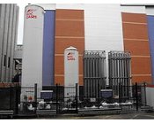 These devices are designed to store and supply liquid oxygen, and are used in most large hospitals, ie when typical requirements are more than 300 l/sec or 7,000,000 l annually.
 The system comprises two banks of at least 10 "G" size cylinders (7,600 l oxygen, 17,000 l N
 A terminal block with a 19 tpi 1/4" male British standard pipe thread is attached to the pipe; it protrudes through the wall plate. While the thread diameter is the same for all gases, the wall connector incorporates a surrounding sleeve that is different for each gas. The example on the right is for the s
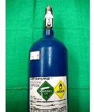 AS 2030 1977. Steel cylinders are hot pressed from bar stock, neck pressed at 400°C, heated slowly to 525°C, quenched in water, and finally aged at 175°C for 8 hours. Typical wall thickness only 3mm. Aluminium alloy cylinders have a 6.6mm wall thickness and are cold pressed.
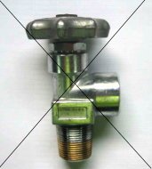 Obsolete Type 10 connection