Chris Thompson USyd Lectures Listing The Anaesthetic Machine - Gas mixing systems OVERVIEW The gas mixing/delivery system lets the anaesthetist control:
Gas mixing systems vary in a number of fundamental ways:
On older full-mechanical machines, the Anaesthetist turns knobs (one for each gas) that directly open or close or open needle valves; the resulting gas flows are indicated on rotameters. The physics and principles of operation of these machines are well understood, however there a number of inherent safety concerns and limitations with their use:
It is likely that electronic gas mixing systems will replace mechanical systems over the next 10-15 years so we all must know about them. An auxiliary (emergency) O2 outlet is always provided. This consists of a shrouded button that delivers approx... 35-70 l/min O2 (but no vapour) to the fresh gas outlet / breathing circuit when depressed.
The needle valve itself has a flat seat so that a complete seal can be made when turning off without damaging any tapered part of the valve and without requiring much force. It is a "constant pressure variable orifice' flow controller. The upstream pressure equals the internal gas supply working pressure, and the downstream pressure is a little above the circuit pressure (basically atmospheric pressure). Mechanical knobs turn anti-clockwise (like your taps at home) to increase flow and electronic knobs clockwise (like a volume knob on a hifi). The oxygen knob is a specialised 8-sided ribbed knob 2mm longer than the others - so that it can be identified by feel alone. The tube is made of tapered conductive (stannous chloride coated) glass, individually calibrated to 20C at atmospheric pressure (+/- 0.5% of full scale reading or 5% of indicated flow). Tubes may be Thorpe type dual-conical tapered single tubes (with a more gradual taper at the bottom for fine control of low flows) or two tubes may be provided for each gas (one for low flows, the output of which enters the high-flow tube). Rotameters are supplied in matched bobbin/tube pairs, the tube being individually hand-marked at each flow for that bobbin. Consequently they are expensive to produce. All rotameters must be strictly vertical to be accurate. Bobbins are fluted to spin so that sticking (which may cause incorrect readings) can be readily detected. O-rings seal the top and bottom. Tubes are protected from accidental damage by a perspex sheet. In Australian machines, the Oxygen knob is leftmost. The bobbin is pushed up by the drag force exerted by friction of the gas on it. This is balanced by the constant weight of the bobbin, which pushes down. Drag force is dependent on the gas flow velocity past the bobbin, which depends on the annular area between it and the tube and the gas flow. Any increase in gas flow would tend to increase velocity and hence drag on the bobbin, causing it to rise up the tube until a new equilibrium point was reached. Under laminar flow conditions, that point would be the point at which the annular area was increased such that flow velocity past the bobbin was the same as before. Whether or not flow is likely to be turbulent is indicated by the Reynolds number. In any given situation, the Reynolds number is proportional to density and inversely proportional to viscosity. Low flows (below 4 l/min) around the bobbin are said to be laminar. Stokes' law pertaining to spherical objects falling in liquids under laminar flow conditions is more relevant than the more commonly mentioned Hagen-Poiseuille equation (Q = Pπr4/8ηl ). Either way, the frictional force on the falling object (drag) under laminar conditions is linearly proportional to both viscosity and velocity of the gas stream. Density has little or no effect on laminar flow drag. Ambient air pressure has no effect on laminar drag because pressure has no effect on viscosity of gas and although it does increase density, density has no effect. Viscosity of gases does increase in proportion to the square root of the increase in absolute temperature, so the bobbin will be a little higher (trivially over-read) at higher temperatures. In contrast, changes in atmospheric pressure (i.e. changes in gas density) should have little or no effect on rotameter position under truly laminar flow conditions. Higher flows are turbulent pr partly turbulent. Drag from turbulent flow is always greater than that for laminar flow. Under turbulent conditions, drag increases in proportion to density (not viscosity) and to the square of the gas flow velocity. Density decreases with increasing temperature, but temperature effects are trivial. Density however increases significantly in proportion to atmospheric pressure. Increasing ambient air pressure should therefore increase drag on the rotameter in a linear manner as well as increasing the likelihood of turbulence at lower flows. Obviously each rotameter must be individualised for the specific gas. They are only accurate at a specified temperature and ambient pressure. In a constant taper rotameter, the distance between flow markers starts to increase past the point at which turbulent flow commences. The generally accepted rule is:
Precise predictions of the impact of changes in ambient pressure on bobbin position cannot be made because of the multitude of factors involved. In particular, the tubes are marked and tapered to take into account of turbulence and annular diameter and there is a non-linear relationship between distance up the tube and flow. Graham's law is often mentioned in relation to flowmeters however it relates to gas diffusion, molecular weight, and the movement of gases through pores and is not directly relevant to rotameters. Ball flowmeters should be read from the middle, and dual-skirt rotameter bobbin from the top. See also this anaesthesiaUK page. I think the statement they make about back pressure dropping the bobbin location is false. Transient back pressure will drop the bobbin only as a result of a transient reduction in flow. Constant back pressure is fundamentally the same as increased atmospheric pressure: at low flows it would have little effect on bobbin location, and at high flows turbulence and density may increase, if anything causing the rotameter position to shift higher up the tube (over-reading).
Anti-Hypoxia Devices These have been 'added-on' to the basic rotameter blocks to prevent inadvertent selection of a hypoxic gas mixture when oxygen is used with nitrous (i.e., all nitrous, for example). They have no effect when air is used as a carrier gas for oxygen. Additionally some of them ensure a minimum absolute oxygen flow rate at low flows to compensate for oxygen-consumption-induced falls in inspired oxygen at low flows.
A pair of levers constrain closure of non-threaded valves. Neither the Oxygen nor the Nitrous knobs are directly connected to their respective needle valves. Requires second stage regulators to maintain equal valve inlet pressures. Assumes a linear relationship between physical needle valve position and flow. If both gases are 'on', closing the oxygen control knob pushes on a lever that is capable of closing both the nitrous and oxygen needle valves simultaneously. The nitrous valve will start to be closed by the lever before a hypoxic mixture can be delivered. Proportioning of the gases depends on their relative distance up the lever. Accuracy at low flows requires fine adjustment of the relative positions of the closed valve seat and the lever.. If both knobs are closed, and the Nitrous knob is opened, no gas will flow because the the oxygen lever keeps the nitrous needle valve closed. Hence if the Oxygen knob is off, turning on the nitrous knob will deliver no gas. Subsequently, opening the oxygen valve will start to deliver both oxygen and nitrous in a fixed ratio. Leaving the machine with the oxygen knob fully closed but the nitrous knob open will stop flow on both rotameters. However a subsequent user who opens the oxygen knob alone (e.g. to pre-oxygenate a patient) will NOT get 100% oxygen. The system may be inaccurate at low flows or as parts become worn over time.
Uses chain-linked gears to physically connect the nitrous and oxygen knobs. When rotating one knob, the other knob will start to turn 'by itself' to prevent delivery of a hypoxic mixture. If both knobs are initially closed, turning on the nitrous knob will turn on the oxygen knob automatically. The system relies on a chain and two gears. The nitrous gear is fixed to the Nitrous spindle, but the oxygen gear can freely rotate on the threaded oxygen spindle. When both knobs are fully closed, the oxygen gear just touches a fixed metal disk that is locked to the oxygen spindle. If the oxygen knob is opened, the gear moves inwards, away from the fixed disk. As the nitrous is then increased, the linking cable causes the oxygen gear to screw itself back up the stationary oxygen spindle thread towards the fixed disk. At the point when the oxygen gear hits the fixed disk, the oxygen knob and spindle will both start to open. If both gases are running, and the oxygen knob is closed while nitrous remains on, the oxygen spindle will screw inwards towards the stationary gear connecting it to the nitrous spindle. At some point the fixed disk on the oxygen spindle will touch the gear, linking the two, and from then on the nitrous will be shut off automatically - in the right proportion. Getting both valves to close completely at the same time requires careful internal adjustment. Note that the gear ratio is 2:1; for the system to deliver the correct gas proportion when active, second stage regulators are required, and the nitrous regulator must be set to a pressure below that for oxygen. Unlike the Ulco system, turning on the oxygen knob will not turn on the nitrous (unless the gear on the oxygen knob is jammed onto its spindle) The system has issues with wear and tear, complexity, inaccuracy at low flows and calibration as does the Ulco system. The chain can break, rendering the system inoperable without this being obvious to the user. The gear and disk on the oxygen knob can jam so that nitrous is unintentionally delivered when 100% oxygen was intended. Dependence on normal operation can lead to 'bad habits such as routinely turning only the nitrous knob on a the start, assuming you'll get 25% oxygen. Sources of Error 1. Atmospheric Pressure True Flow = Indicated Flow / Sq.root of atmospheric pressure diff In a hyperbaric chamber, flowmeters over-read; gas in the tube will be 'thicker', so the bobbin is pushed higher up the tube for any given flow. e.g. at 2 ATA, an indicated flow of 5.6 l/min is actually closer to 4 l/min (5.6/√2 = 5.6/1.4 = 4). Conversely, at altitude, flowmeters under-read; he gas is 'thinner', so the bobbin is not pushed as far up for a given flow. Hence at 0.5 ATA, an indicated flow of 4.0 l/min is actually about 5.6 l/min. At low flows these effects may be less of an issue because laminar flow is unaffected by density (pressure). 2. Wrong gas Heliox (80% He, 20% O2) is 1/3 the density of O2. Under-reads by a factor of about 1.7 times at high flows, but reads approximately true at low flows, since viscosities are nearly identical. N2O and CO2 are almost interchangeable. CO2 has twice the viscosity of cylcopropane, so at low flows, cyclo through a CO2 rotameter under-reads by half.
A failure of an upper o-ring will not be detected by the flowmeter. If O2 is the last to enter the gas stream, a leak in the air or N2O seals will not cause hypoxia. Hence O2 functionally enters last into the common outlet tube. In the US this means that the O2 knob is at the right, whereas in Australia it is at the 4. Sticking 5. Float unnoticed at top of tube 6. Change in supply pressure / dirt in needle (unintended flow change; reads true) 7. Knob bumped accidentally etc 8. Gas flow fails totally if oxygen supply fails ELECTRONIC GAS MIXING SYSTEMS Electronic systems feedback control the internal flow control unit, making frequent minor adjustments so that the delivered flow is whatever you've asked for. Gas supply pressure changes, atmospheric pressure changes or partial valve occlusions have no effect on delivered flow. They cannot be bumped accidentally, are not affected by tipping, sticking or leaks, and the display can be easily read in dim light, as well as being set with a high degree of precision. Usually they are self-calibrating, and a second redundant computer system monitors the primary system to check for software errors. On ending the case, all flows are turned off, and at start-up the machine always enters a known state - no more accidentally leaving the gases on all weekend or starting a case with a flow tube at the top. Internal flow sensor failures are usually detected the instant they happen by comparing the sum of the inflows of each individual gas to the total outflow of the combined mixture; they should add up properly. If not, the system will let you know. Finally, if Oxygen and/or Nitrous fails, they can automatically switch to air at the same flow you had. A backup system is desirable in case the electronics fails. It should permit manual metering of a 100% O2 gas supply via the vapouriser. In practice, the operator just sets the Fresh Gas Oxygen as % and the total Fresh Gas flow in l/min as independent variables. They are accurate to very low flows. You can select either air or nitrous as carrier gases. A software algorithm performs 'anti-hypoxia' actions such as preventing the selection of hypoxic fresh gas mixes as well as setting a limit on the minimum oxygen flow rate at very low flows (to compensate for the effect of O2 uptake at low flows.
The Drager Julian and Primus machines use fuel-injector type on/off valves to inject small pulses of gas direct from each of the the 400kPa internal lines into a 500ml container. The volume of each pulse is known, and they are feedback controlled to (a) provide gas in the correct proportions and (b) to ensure that the container pressure is maintained constant at about 200kPa. Another valve deliver the correct total fresh gas flow from the reservoir (again in very small pulses). If the operator needs a rapid change in gas composition, the chamber is flushed, but occasionally there can be a slight delay in seeing a change in composition at the fresh gas outlet. The Datex Avance mixer uses fully proportional flow valves to directly meter the gas flow directly into the circuit - just like having someone twiddling the knobs inside the machine for you. There is no reservoir. The actual position of the mechanical parts of the valve is irrelevant; they are continually adjusted to ensure the delivered flow is what you set. Problems ? Unfamiliar user interface - potential for abrupt failure of gas delivery. Otherwise they generally just do exactly what they are supposed to do. Fresh Gas Failure in electronic machines Usually annunciated by specific electronic alarms. These alarms may sound the same as a whole bunch of minor 'nuisance' alarms. May or may not have small backup / reserve gas supplies. Usually automatically switch to the next most appropriate of the available gases.
See Also: Equipment notes by Mark Finnis |
||
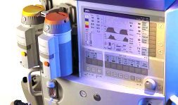 On newer machines, the Anaesthetist adjusts gas flows via an electronic control knob as part of a computerised user interface, and the actual gas mixing is performed by computer controlled valves (either pulsed on/off solenoid type or proportional flow type) deep inside the machine. Set values and delivered gas flows are indicated on a colour screen. Usually some electronic equivalent of a rotameter is displayed to indicate what is happening, and additionally there is usually some iconic representation that gas is actually flowing (analogous to the spinning of the bobbin). However often there is no flow tube to physically indicate flow. Advantages of electronic gas mixing systems include:
 ROTAMETER BANKS